WebRelay: A remote controlled power switch board - Part 3
Once the relay system was up and ready for daily use, I set it up in my office and attached the devices to the relay modules. It was good and accessible to others through the office network. But there was a drawback that I noticed.
This current solution was not movable since it was required to be connected to the desktop through the serial communication adapter. Because of this, the relay system had to be set up close to where the desktop system was placed.
Adding mobility to the Board
The best solution to this issue was suggested by a senior at work. He suggested to move to a NodeMCU to control the relay setup. But this would require a big change in the circuit. But because of his suggestion, I found the next best thing. I bought an ESP01 and added it to the circuit.
Adding ESP01 to the board needed extra components like two extra resistors to set up as voltage divider and a 3.3V regulator chip for powering the ESP module. ATmega328 worked with 5V but ESP01 required 3.3V. Also, the ATmega chip now received power from the external 5V supply since the USB-Serial converter was not removed from the circuit.
My senior suggested to use MQTT to communicate with the web server as it is the defacto standard in industrial applications. I started the initial development with MQTT but I felt that, for this light weight application, using a simple web server with API that allows an external client to send data to the board would be the easiest and hackable solution.
So I set up a tiny web server and connected it to the wifi network using the ESP01 module. On receiving json data about state of the relays, it parsed the values and passed it to the ATmega chip using UART connection. No code change was necessary in the ATmega chip since it received data similar to how it worked with the USB Serial converter in the previous implementation.
There was an issue with finding the board’s IP. For this I had two options:
- Send a broadcast UDP message to find the ESP device.
- Cycle through all 254 devices in the network, sending GET requests until we get a response.
The first solution was actually the better one generally since it was a simple process. But I could not get it to work due to the UDP communication issue between wired and wireless devices in the network. And since it was an office network, I could not change it’s settings.
So I had to use the second way to get the IP of the relay board. I added an endpoint to the ESP server that responds with a success status and a custom message that confirms that this is the ESP that we hit.
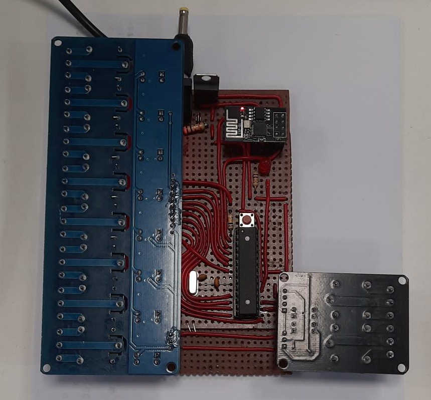
After modifying the circuit to include the ESP01 module for WiFi, the final circuit
board was ready to be deployed. The next big thing was to improve the backend server.