WebRelay: A remote controlled power switch board - Part 1
Controlling power remotely shouldn’t require expensive smart plugs or overly complex automation systems. I wanted something lightweight, reliable, flexible, hackable and completely open—so I built it from scratch.
This is the first post in a blog series documenting the process of ideating, designing, and building a custom solution to meet the needs of myself and my colleagues. This will be a bit long that mentions the mistakes and upgrades I added to the project during each stages. So feel free to skip through portions that you feel as less important.
The Spark
This all started at work when my coworker was testing a remote server. She wanted to turn off the system for a time period and turn it back on. But since she was working from home, there was no way she could test this without asking for help from others who would be available on-site. But what if no one was available when she needed it?
There should be a way to resolve this issue, right? Maybe a power switch that can be controlled from anywhere? A smart switch with a UI?
This idea reignited my passion for hands-on engineering. I went back to my old university projects and write-ups for inspiration. I dug out my trusty Arduino Uno from the tinkering kit I hadn’t touched in years. As tradition goes, I flashed the Blink program to test if the board was still alive.
It was time to create a test circuit with a small relay module to see if my plan would work.
The Prototype
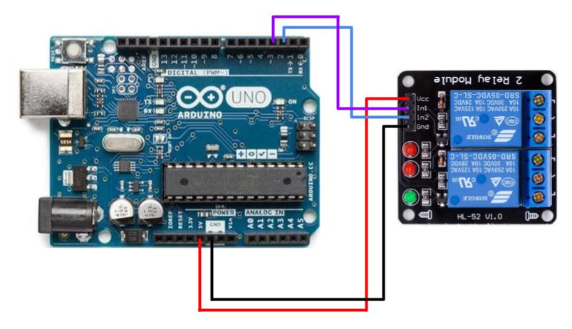
Components
- 1 × Arduino Uno Development Board
- 4 × Jumper Wires (Male-to-Female)
- 1 × 5V 2-channel Relay Module
Circuit Diagram
Arduino Program
const RELAYS[] = [2, 3];
const COUNT = sizeof(RELAYS) / sizeof(RELAYS[0]);
bool isActive = false;

void setup() {
    // Set relay pins as OUTPUT pins
    // Initialize all Relays in OFF state
    // Note: By default, most RELAYS are ACTIVE LOW
    for (int i = 0; i < COUNT; i++) {
        pinMode(RELAYS[i]);
        digitalWrite(RELAYS[i], HIGH);
    }
}

void loop() {
    for (int i = 0; i < COUNT; i++) {
        digitalWrite(RELAYS[i], isActive ? HIGH : LOW);
        delay(1000);
    }
    isActive = !isActive;
}
The above program toggles both relays in a pattern with a delay of 1 second for each relay.
The next part was to toggle the relay to some user input. And since I wanted to implement a remote controlled switch, I chose serial communication to transfer user input to the arduino and the arduino would parse the input to toggle the relays accordingly.
const RELAYS[] = [2, 3];
const COUNT = sizeof(RELAYS) / sizeof(RELAYS[0]);
String str = "";

void setup() {
    // Initialize serial communication
    Serial.begin(9600);
    // Set relay pins as OUTPUT pins
    // Initialize all Relays in OFF state
    // Note: By default, most RELAYS are ACTIVE LOW
    for (int i = 0; i < COUNT; i++) {
        pinMode(RELAYS[i]);
        digitalWrite(RELAYS[i], HIGH);
    }
}

void loop() {
    if (Serial.available() <= 0) return;
    str = Serial.readStringUntil('\n');
    str.trim();
    int separatorIndex = str.indexOf('_');
    if (separatorIndex == -1) {
      return;
    }
    int relay = str.substring(0, separatorIndex);
    if (relay.toInt() > COUNT) return;
    String stateStr = input.substring(separatorIndex + 1);
    digitalWrite(RELAYS[relay.toInt(), (stateStr == "ON") ? LOW : HIGH);
}
This made it possible to control the relay switches from the serial monitor
by sending 0_ON, 1_ON, 0_OFF and 1_OFF.
Outcome
This was just to get a quick dopamine boost before diving into the constraints and challenges of this project. With that accomplished, I decided to expand it into version 0 of the project.