WebRelay: A remote controlled power switch board - Part 2
Once the initial test project was successful, I started planning to build a custom
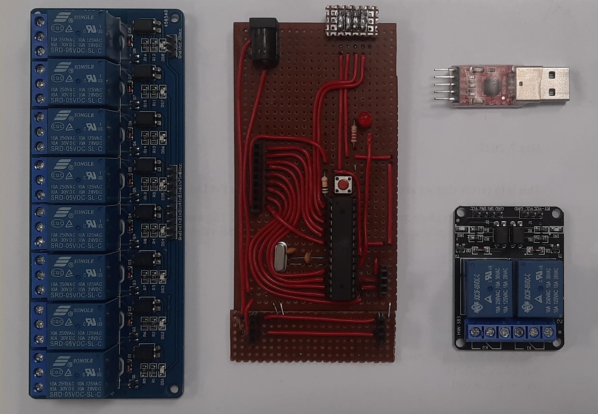
circuit board with a standalone ATmega328 chip to create the relay system.
Building a Custom Circuit Board
The main features for the circuit that I wanted to design were:
- have a reset button
- have dedicated I/O pins for 10 relays
- have a connector to attach serial communication module
- have an LED that would blink when receiving data from the serial device
Things I did not want to implement in the board was:
- do not save current state of the relay in board memory
- only echo the received data to acknowledge
There are several guides online on how to set up a standalone circuit for arduino. By referring the official guide, I implemented a circuit with ATmega328 chip.
The ATmega chip I bought was having bootloader pre-installed, making the process easier for me. But I think you can buy chips without bootloader pre-installed if you want to get them cheaper.
I bought a CP2102 USB to TTL Serial Adapter to communicate with a server. But in my opinion, its better to go with an FT232RL adapter since it has better driver support and much easier to work with.
I chose to power the ATmega chip through the serial adapter and the relay modules were powered through a separate 5V power supply. This was to make sure that the microcontroller is isolated from any abnormalities which may occur in the relay modules’ power circuit.
Communication with a computer
I preferred to control the relays through a Desktop PC with short messages. So I decided to encode the states of the relay in binary format.
0 represents OFF state
1 represents ON state
This way I can send just numbers to represent the states of the relay set. Assuming we need to turn on second and fourth relays, I construct the data as follows:
Binary : 0000001010
Decimal: 2^3 + 2^1
       = 8 + 2
       = 10
If we need to turn on the middle 4 relays, the data will be:
Binary : 0001111000
Decimal: 2^6 + 2^5 + 2^4 + 2^3
       = 64 + 32 + 16 + 8
       = 120
Implementing this logic was straighforward using arduino programming language. After setting up the circuit and flashing the chip with this program, I got the relay system to work by sending data directly from the arduino serial monitor.
Server Implementation for UI
For the server part, I planned to create a web frontend that shows the 10 relays and it’s state. I managed to create a table that shows all 10 relays as 10 different rows in a single html file. The rows contained columns for the user and a toggle button to switch the relay ON and OFF.
On toggling, the UI asks for the name of the user. After entering the name, the frontend sends the relay ID, username and toggle state to the backend server.
For the backend, I created a simple python web server using flask that serves this html file. The server stores the states of the relay system. The server, when receiving the data from the frontend, updates the internal state accordingly and then transmits the updated relay states to the relay board using serial communication.
Communicating with serial devices through the python script was not as smooth as I expected since it required meddling with the permissions and installing drivers for the CP2102 serial adapter device.
Once the script was up and running as expected, the relay system was ready for use.